
complete system based on one or more ESEAT and all elements to safely conduct lightning to earth in order to protect a structure, facility or open area against direct lightning impact.
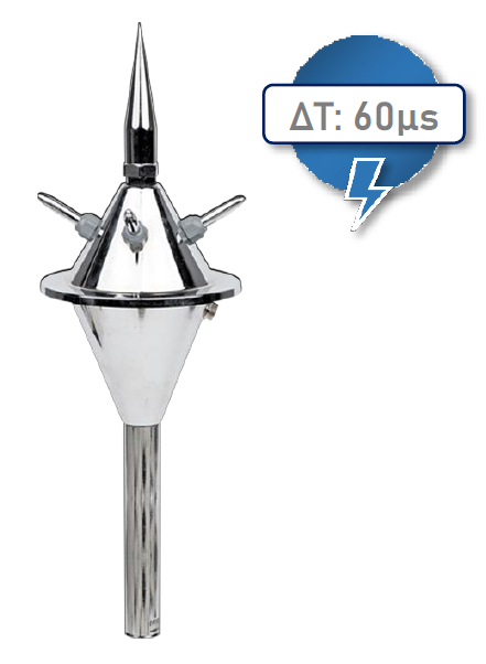
air terminal generating a streamer earlier than a simple rod air terminal when compared in the same conditions NOTE - An early streamer emission air terminal is made up of a striking point, an emission device, a fixing element and a connection to the down conductors.
difference expressed in micro-seconds between the emission time of an ESEAT and an SRAT measured in a laboratory under the conditions defined in this standard.
LPS with an air-termination system and down-conductor system positioned in such a way that the path of the lightning current has no contact with the structure to be protected NOTE: In an isolated LPS, dangerous sparks between the LPS and the structure are avoided
permanent damage of electrical and electronic systems due to LEMP
minimum peak value of lightning current that will cause damages
The need for protection is determined according to many parameters including the lightning flash density of the considered area. A risk analysis method is proposed in Annex A. The lightning flash density is given in annex B or by local data including for example detection network, maps and statistics. NOTE 1: Other considerations may lead to take the decision to adopt protection measures for reasons other than statistical ones. For example, compulsory regulations or personal considerations since some factors cannot be estimated: the wish to avoid risk to life or to provide safety to the occupants of a building may require the use of protection, even though the calculated risk is under the tolerable level.
NOTE 2 Different normative documents give some risk analysis methods that can be used.
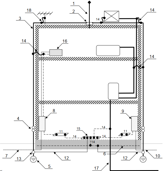
The installation may be composed of the following elements:
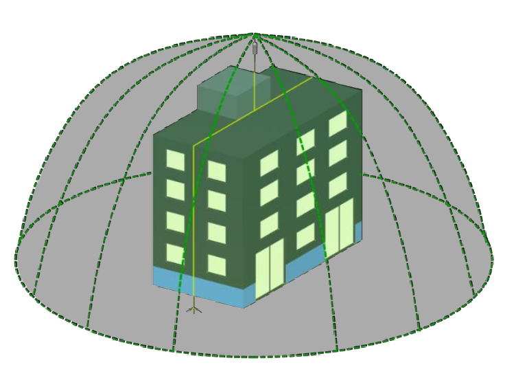
ESE lightning rods use active ionization system that allows to have a larger protection radius when compared to conventional lightning rod systems. The installation of an ESE lightning rod should follow a different criteria from Faraday Cage method.
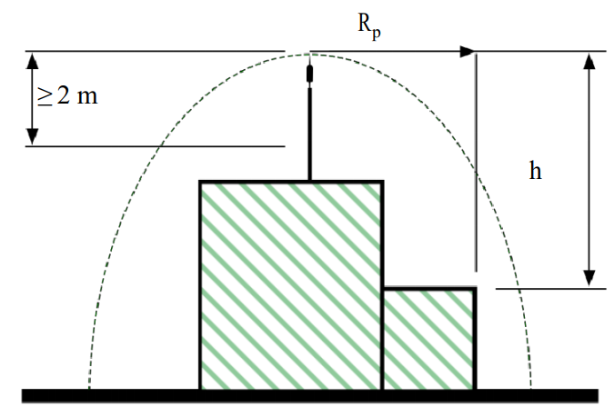
The protection radius of an ESEAT is related to its height (h) relative to the surface to be protected, to its efficiency and to the selected protection level
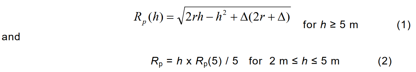
Calculation is based on standards NFC17.102:2011 and UNE
21.186: 2011. Please view the norms for complete technical details
1.1 After specifying the protection level, you can choose the appropriate model of ESE lightning rod using the following protection radius (Rp) table:
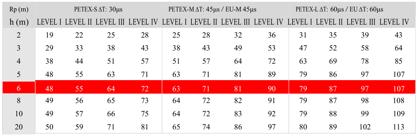
INDEX ΔT: Early streamer emission of an ESE lightning rod, determined by laboratory tests.
LEVEL: Level of protection required by a particular building, depending on the operations carried out and various other factors.
h (m): Distance between the lightning rod and the roof level, optimal:6 meters.
STANDARDS
NFC17.102:2011
UNE21.186:2011
TS EN62305
1.2 The first column of the table Rp(m) indicates the elevation of the ESE lightning rod above the highest point of the structure within the protection zone.
1.3 To obtain elevation, a mast, pole, tower, or part of the structure (such as chimney, antenna, etc.) must be used.
1.4 The minimum elevation should be 2 meters. The optimal level of elevation is5 or 6 meters, because below that level the radius of protection decreases rapidly and above that level, the increase is very limited.
1.5 It is recommended to install the ESE lightning rod at one point to cover the maximum area. To specify the installation point, the top plane of the building roof can be used.
• Cost-effective solution
• Provides an active protection to the whole building
• Protects surrounding areas
• Requires less conductors and earthing accessories
• Easy to install and maintain, requiring less workforce
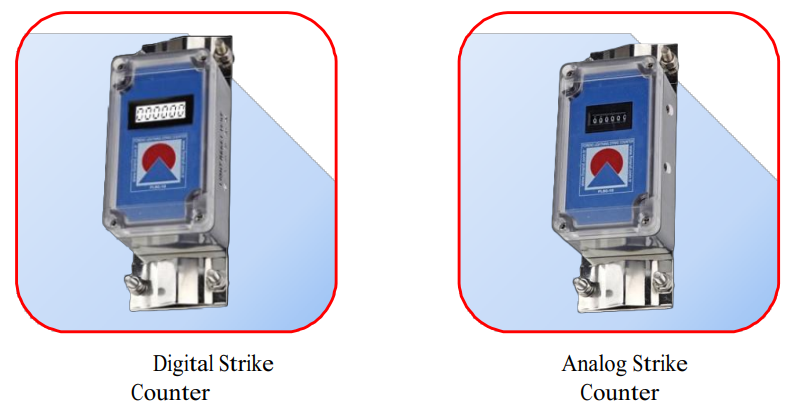
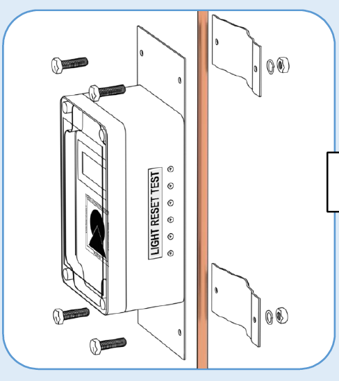
A lightning strike counter is used to count the number of strikes. It should be installed on the mast or wall, directly on down conductor and above the test clamp and, in any case, at height about 2 meters above the ground level. It shall comply with EN 62561-6.
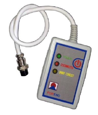
Tester lets you check the status of your ESE lightning conductor. With TESTER, you are able to check if there is a short circuit or a fault in the ion generator immediately by simply connecting the cable to the ESE conductor and pressing the button on the testing device.
When pressing the button, the GREEN LED indicates full
functionality, the RED LED indicates the device is not
properly connected and the YELLOW LED indicates there is a short circuit
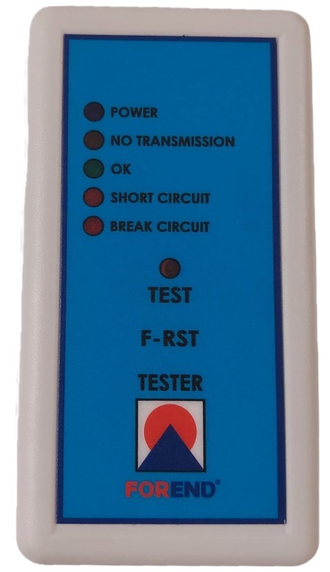
Solar Tester let you test E.S.E. terminals remotely. The testing device stores energy to operate for 24 hours by a daily exposition of 5-7 hours of sun light
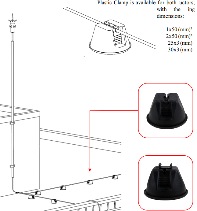
Available in plastic or other materials, this accessory serves to keep the cable suspended on a flat surface and avoid contact with unwanted objects.
Each down-conductor should be provided with a test joint in order to disconnect the earth termination system for enabling measurements.
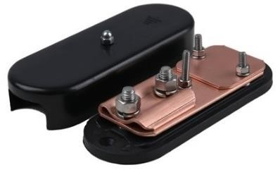
Test joints are usually installed at the bottom of the down-conductors.